Tried to do Bayer-dither with Unity Shader Graph
I don't know the node which returns screen position among blender's Composite nodes. (Please let me know if there are.) But I found Unity has the node which called just as it does, 〈Screen Position〉.
I thought 「the node make possible the Bayer-dithering reduce color method?」 After struggling it, I guess somehow I managed it. So let me show you the way I've done. But please tell me if you know smarter way since it's obviously not an elegant way at all.🙇
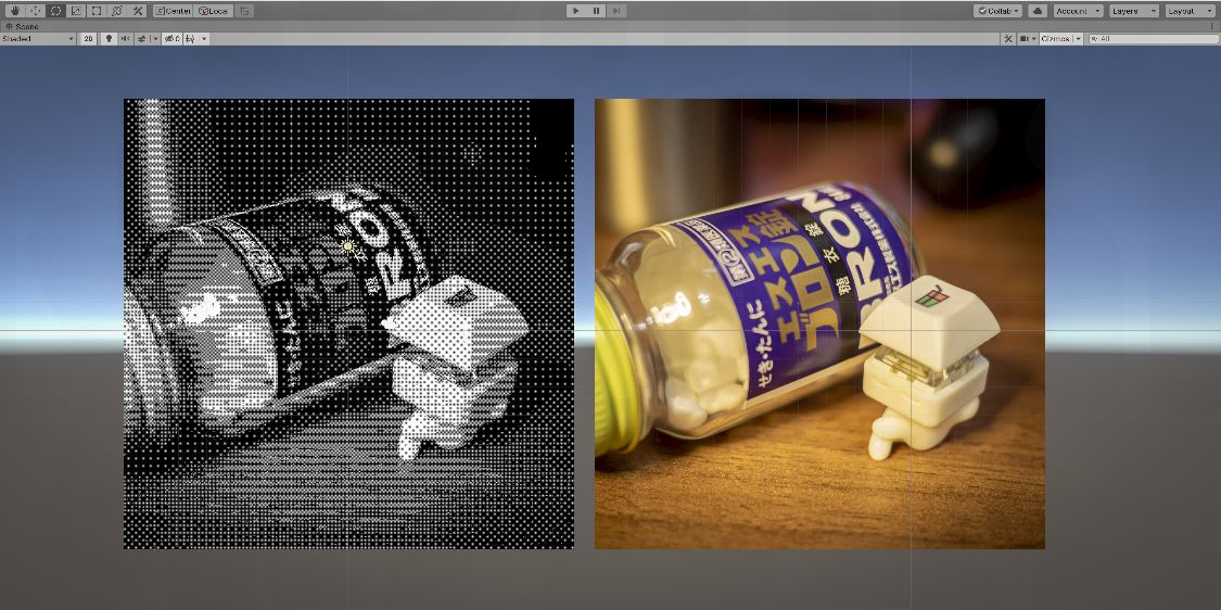
This is the result applied on the sprite of Keycappie with Bron (my essential medicine). Right one is original photo and left one using the shader graph which I made. Although having moire fringe as it's not actual pixel size in Game view, beautifully reduced to black and white 1 bit palette.
What is Bayer-dithering?
Let me explain what the Bayer dithering is first. If you know what is it already, please skip to the next section.
If I roughly explain it, one way of dithering method for reducing image colors. It is “Pattern dither” in Photoshop. For example, when reducing the color palette to black and white, applying a pattern (something like a matrix) called Bayer filter to each pixel and use its value as threshold. If the pixel luminance is higher than the threshold, make the pixel white and make it black if it's not. Then the image become only black and white with mysterious patterns with keeping its looks. It's incredible isn't it?
This method dropping the differences between the pixel luminance and the threshold so the result is not beautiful as Error-diffusion dither. But still, I love the nostalgia from unique patterns. The Pocket Camera of Gameboy, everybody loves, is using this method too. (Actually I'm not sure, but the patterns on it's photo looks same so I guess it's correct)。
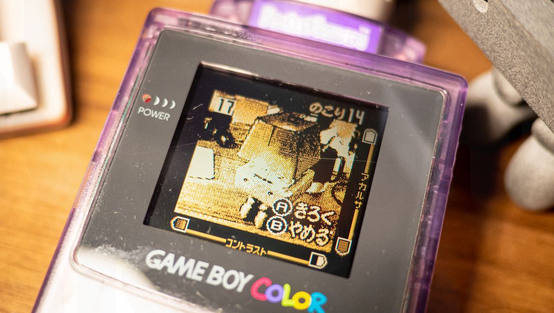
21 years old digital camera which works perfectly by only replacing its batteries. Don't even compare to lithium-ion battery devices that become completely dead by leaving it alone only a few years.
Overall view of the Shader Graph
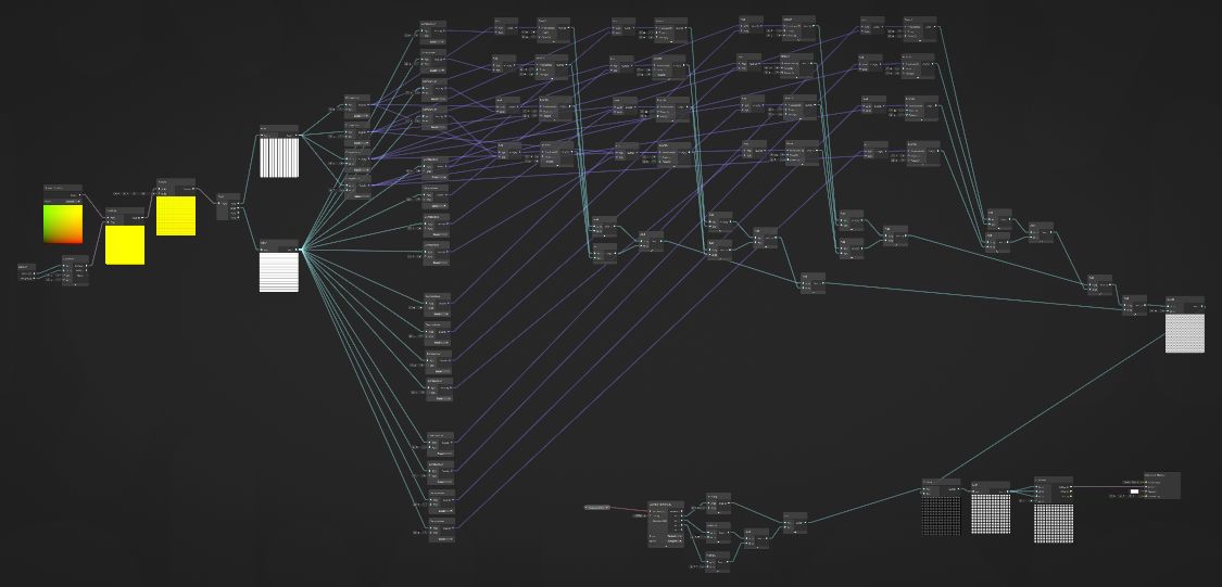
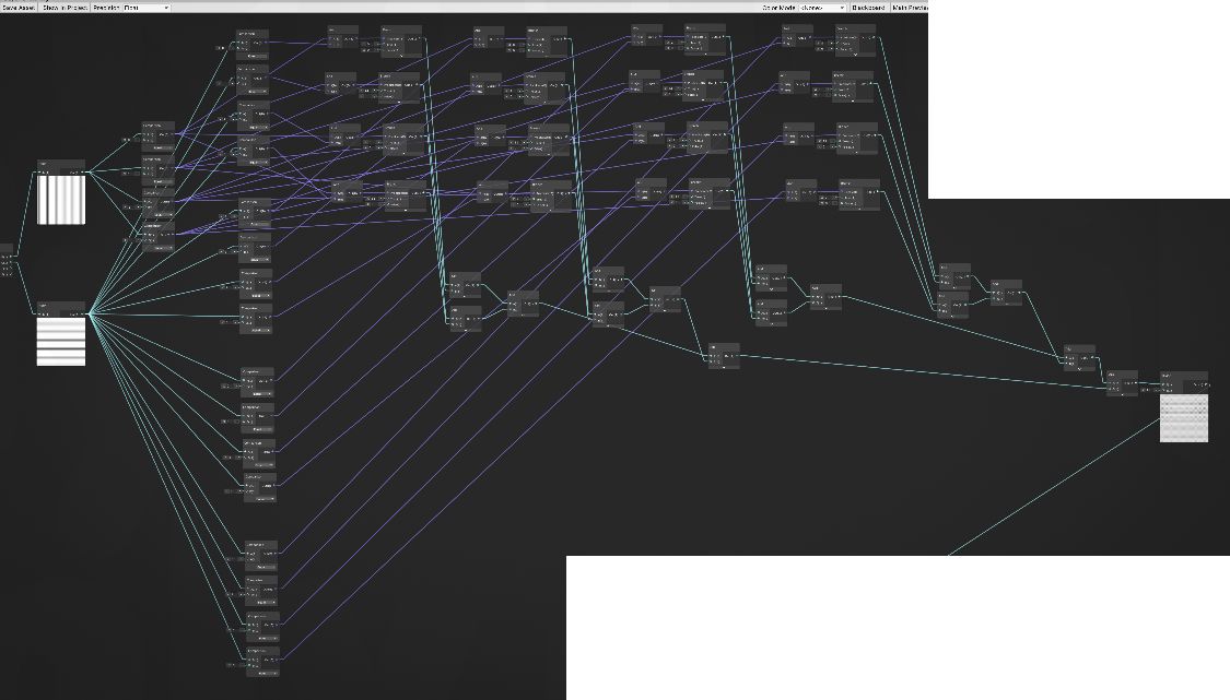
So, this is the shader graph overall. What it does is simple but the area getting bayer-filter threshold became large. Small last part comparing threshold and pixel value. And then outputs black or white. It's a shader for 2D sprite, by the way.
Getting screen position and position for bayer-filter
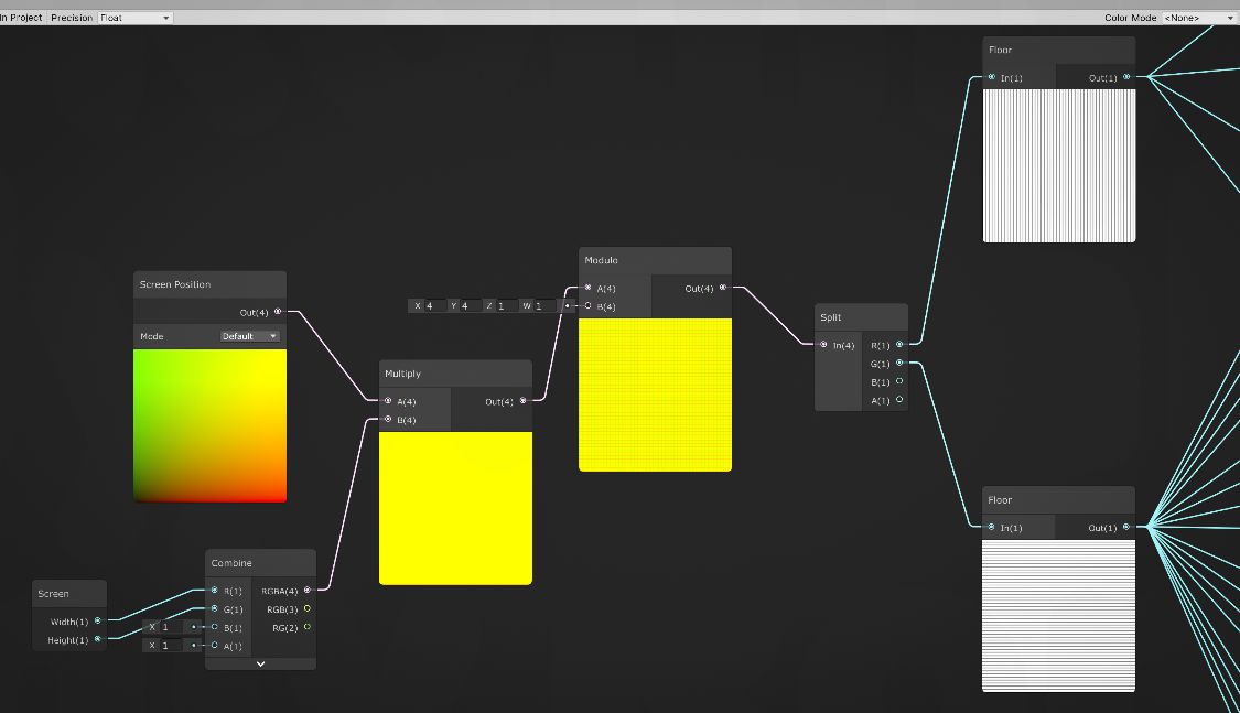
This first part is getting screen position of sprite. I thought 〈Screen Position node〉 outputs pixel XY position, but actually the values are normalized as 0..1.0. So I used 〈Screen node〉 to get screen size and convert to pixel unit by multiplying them.
After succeeding to getting pixel coordinate, get modulo with 4 for X and Y, to make them reference position for bayer-filter. For this, using 〈Floor node〉 to make them Int after splitting the vector to X and Y. With this all values became integer of 0..3. Only the process remain is getting bayer-filter value and compare it to the pixel value.
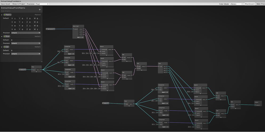
Getting a value from specific location in the bayer-filter
Bayer-filter is simple 4x4 matrix so I thought I should use Matrix4x4 node first, but I couldn't figure out how to get a value from specific location from the matrix.
So, it looks dumb way but I combined 〈Comparison node〉, 〈And node〉 and 〈Branch node〉 to do like ["First row, first column value if X = 0 and Y = 0", "Second row, first column value if X = 0 and Y = 1", "Third row, first column value if X = 0 and Y = 2"..., "First row, second column value if X = 1 and Y = 0"...] I repeat them 16 times with simple honestly. Each outputs 0 if the condition doesn't meet. Thus adding up all values from 16, means that I could get the value from desired position in bayer-filter.
Additionally dividing extracted value with 16 for matching scale and comparing, to pixel value.
Getting pixel RGB and making it grayscale
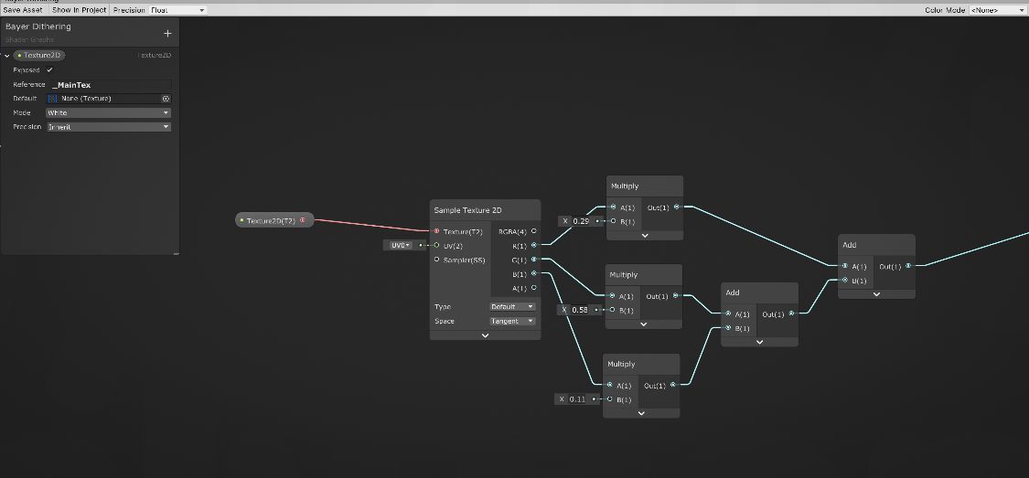
On the other hand, this part is getting a pixel value which should be compared with bayer-filter. Looks like sprites pixel value can be extracted by
〈Sample Texture2D node〉 which set Reference as "_MainTex" and connected to
〈Texture 2D Input node〉.
Next step is converting RGB value to grayscale as preparation for comparing to bayer-filter. I used common formula for grayscale which is R * 0.299 + G * 0.587 + B * 0.114.
Grayscale - Wikipedia
https://en.wikipedia.org/wiki/Grayscale
Comparing bayer-filter value to pixel value, and outputting black or white
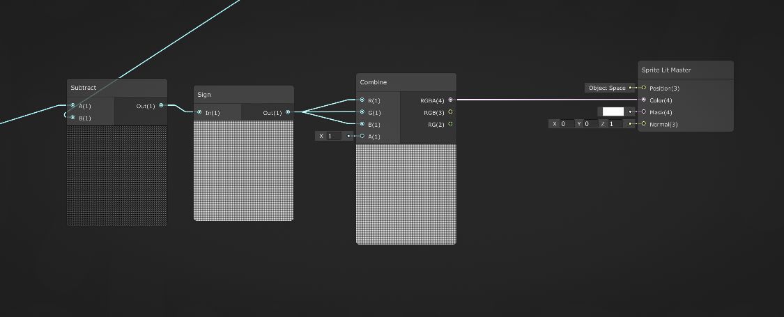
Lastly subtracting B which is bayer-filter value from A which is pixel value, for comparing them. It become positive value if the pixel value is higher than the threshold, and become negative value if it's lower. Then convert it to -1 or 1 by using
〈Sign node〉, and providing it to each RGB channel to make white or black color and it goes color port of final
〈Sprite Lit Master node〉. Seems -1 clamped to Black(0).
Result
Aside the ugly looks of the shader graph, I assume the bayer-dithering itself is succeeded. I'm not certain but at least it looks so.
I'm in studying the Shader Graph still. I learned 〈Sub Graph〉 while writing it and I guess it can make the graph itself simpler. For example, this graph has not a few Add-nodes to sum three or four values. I think making sub-graph like "Sum multiple values" will work fine.
この記事はここで終わりです。
読んでいただきありがとうございました。
良かったらシェアしてね!
That's all for this article. Thank you for your reading.
Please share this if you like it!